This is the second article of an ongoing series about game development for the Web. In the first article, we talked briefly about the <canvas> HTML element, our Web based painting fabric and the portal which makes possible conveying to the user a game experience.
In this delivery, we will discuss the graphics pipeline, that is, the order in which we process data before rendering anything on the screen, and the rendering context. These are major concepts in computer graphics and understanding them will become crucial moving forward in the series.
The graphics pipeline
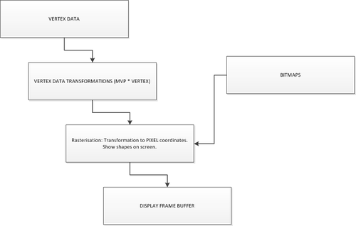
In computer graphics, the word render is the process of generating an image on your computer screen from a geometric object. Rendering, is a multi-step process, often described in terms of a graphics pipeline.
At the start of the pipeline, we feed in polygon (triangle) vertices and color information about them (which represent the models that comprise a scene), bitmaps to paint onto some of the scene objects or use as backgrounds, and perhaps some locations of lights. At the other end of the pipeline a two-dimensional color image appears in a memory location called the frame buffer.
The paint brush
Ever since the early days of real-time graphics rendering, the triangle has been the paintbrush with which scenes are drawn. Although modern GPUs can perform all sorts of flashy effects and calculations to cover up this dirty little secret, underneath all, triangles are still the geometric objects with which they work.
The space transformations
There are several different coordinate systems associated with the rendering pipeline. The vertices of a model are typically stored in object space or model space, a coordinate system that is local to the particular model and used only by that model. The position and orientation of each model are often stored in world space, a global coordinate system that ties all of the object spaces together. Before an object can be rendered, its vertices must be transformed into camera space (also called eye space), the space in which the x and y axes are aligned to the display and the z-axis is parallel to the viewing direction. It is possible to transform vertices from model space directly into camera space by concatenating the matrices representing the transformations from model space to world space and from world space to camera space. The product of these transformations is called the model-view transformation. The Matrix Multiply step transforms the controlling vertices of our polygons, into rotated or translated locations away from their standard positions through these different spaces.
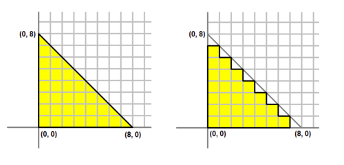
Rasterisation
The rasteriser takes each triangle, clips it and discards parts that are outside of the screen, and breaks the remaining visible parts into pixel-sized fragments. The outputs are also interpolated across the rasterised surface of each triangle, assigning a smooth gradient of values to each fragment.
The location into which we draw these pixels is the frame buffer. If we have some bitmaps that we want to use, say as backgrounds, we copy them into the frame buffer during rasterisation step. The raster operator tends to combine several bitmaps in an operation called bit blip, which stands for bit-level block transfer.
Usually the frame buffer is an off-screen memory bitmap or a RAM region on the graphics card, as it is too visually disturbing to see the drawing happening bit by bit. Once the pipeline finishes filling the frame buffer, the Display Frame Buffer step makes the frame buffer image appear in a visible window. When the hardware allows it, the buffer is displayed using a techniquecalled page flipping or buffer swapping.
The idea behind buffer swapping is that, rather than moving the pixel information from one region of memory to another, you simply change the address that the graphics card uses as the base location from which to refresh the visual information in your window. Doing buffer swap for an onscreen window is harder than doing it for an entire screen, but newer graphics cards and graphics libraries allow this.
It is important to note that, in the 2D rasterisation step, the graphics system draws directly into the frame buffer. However, when rasterising a 3D scene, the system draws into an intermediate buffer called the Z-buffer.
In conclusion, the graphics pipeline describes the transformation of a vertex buffer that defines the polygons of our scene into a frame buffer, which is what is finally rendered into the screen. Of course, this operation is intensive and requires multiple passes in order to reflect changes in the scene and transformations of the shapes involved in it.
The Rendering Context
The rendering context is where all the pieces of a graphic library come together to actually display bits on an output device. As such, the rendering context implementation is unique to each type of output device. In the <canvas> element, the renderings context main role is to transform geometrical primitives to bits. In addition, it has to do state management of things like font, transformations, colors, etc. A render context can be thought of as the set of brushes and rules used to draw the game world. The <canvas> element can only have one rendering context per instance.
The browser window itself is managed by a rendering context which rules for showing stuff are given by a famous markup language called HTML.
Since the rendering context is the focus point for manipulating bits, there are additional methods for creating off-screen drawing surfaces and managing double buffering. The context API, as is called in the <canvas> element, handles the double buffering automatically for us as well as many other operations that happen off-screen.
Conclusion
It is very important to understand what the API does for us and how things get into our screen. This way we can optimize the handling of our geometric objects before feeding them to the frame buffer. Initially most of these considerations will not be taken into account since the CanvasRenderingContext2D will take care of everything for us, but as we move forward into WebGL, by design we will have more control over the way things get drawn into the screen.
References
Weisstein, Eric W. “Coordinate System.” From MathWorld—A Wolfram Web Resource.
http://mathworld.wolfram.com/CoordinateSystem.html
Groff, Joe “An intro to modern OpenGL. Chapter 1: The Graphics Pipeline”
http://duriansoftware.com/joe/An-intro-to-modern-OpenGL.-Chapter-1:-The-Graphics-Pipeline.html